How a swivel ball joint is made?
Swivel ball joints, often referred to as ball and socket joints, facilitate pivotal movements in mechanical linkages. Understanding their manufacturing process is essential for engineers and manufacturers aiming to produce reliable and efficient components. They are critical mechanical components used across industries to enable rotational movement while maintaining fluid or structural integrity. They are integral to systems requiring rotational flexibility. Whether in hydraulic systems, automotive suspensions, or industrial machinery, these joints must withstand high pressures, heavy loads, and harsh environments. This guide explores the step-by-step manufacturing processes, key materials, and quality control measures involved in creating durable and reliable swivel ball joints.
Understanding Swivel Ball Joints: Basics and Applications
1. What is a swivel ball joint
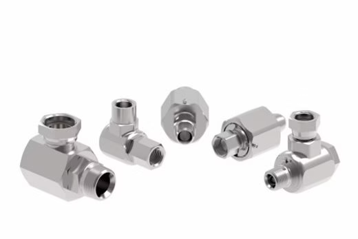
A swivel ball joint, also known as a rotary joint or swivel coupling, allows two connected components to rotate freely around a central axis. Their design and manufacturing require precision engineering to ensure durability, leak-proof performance, and resistance to extreme conditions. This motion prevents hose twisting, reduces mechanical stress, and ensures efficient fluid transfer in dynamic systems.
2. Common applications
Swivel ball joints are utilized in various industries due to their versatility and functionality. Some common applications include:
2.1 Automotive Industry
In steering systems, swivel ball joints facilitate the movement of the wheels in response to steering inputs, ensuring precise handling and maneuverability.
2.2 Industrial Machinery
They are used in machines that require rotational movement, such as conveyors and robotic arms, to allow for flexible positioning and operation.
2.3 Aerospace and Defense
Swivel ball joints are employed in control systems of aircraft and spacecraft, enabling precise adjustments and movements of control surfaces.
2.4 Medical Devices
In medical imaging equipment and surgical instruments, swivel ball joints provide the necessary range of motion and stability.
3. Design Considerations
Designing an effective swivel ball joint involves several critical factors:
Load Capacity: Ensuring the joint can handle the expected forces without failure.
Range of Motion: Determining the necessary angular movement to meet application requirements.
Lubrication: Incorporating features that allow for proper lubrication to minimize wear and maintain performance.Environmental Resistance: Designing for resistance to factors like corrosion, temperature extremes, and exposure to harsh chemicals.
Addressing these considerations during the design phase leads to more reliable and efficient swivel ball joints.
Key Steps in Swivel Ball Joint Manufacturing
1. Material Selection
The performance and longevity of swivel ball joints heavily depend on the materials used in their construction. Common materials include:
1.1 Steel Alloys
High-strength steels are often used for their durability and ability to withstand heavy loads.
1.2 Stainless Steel
Chosen for its corrosion resistance, stainless steel is ideal for applications exposed to harsh environments.
1.3 Aluminum Alloys
Lightweight and strong, aluminum alloys are suitable for applications where weight reduction is essential.
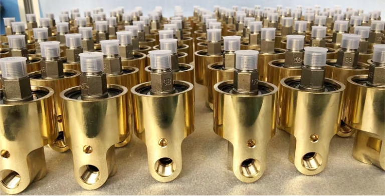
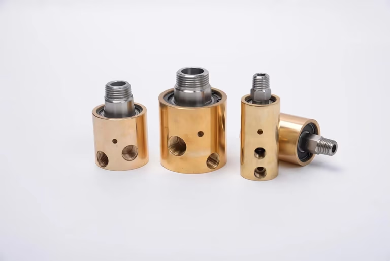
1.4 Bronze and Brass
These materials offer good wear resistance and are commonly used in applications requiring low friction.
2. Precision Machining
The sleeve and body are precision-machined to tight tolerances to ensure smooth rotation and leak-free operation. Processes include:
2.1 Forging and Casting
Hot Forging: Raw metal billets are heated to 1,200°C and shaped under high-pressure dies to form the joint’s body. This enhances grain structure and mechanical strength.
Investment Casting: For complex geometries, molten metal is poured into ceramic molds, producing near-net-shape components with minimal post-processing.
2.2 Precision Machining
CNC (Computer Numerical Control) machining ensures micron-level accuracy:
Turning: Lathes shape the outer diameter and internal bores.
Milling: Multi-axis machines carve grooves, threads, and sealing surfaces.
Grinding: Achieves surface finishes of ≤0.4 µm Ra for sealing interfaces.
2.3 Heat Treatment
Quenching and Tempering: Increases hardness and wear resistance.
Case Hardening: Applied to ball studs for enhanced surface durability.
2.4 Surface Finishing
Electroplating: Zinc or nickel coatings prevent corrosion.
Passivation: For stainless steel, nitric acid treatments remove free iron particles.
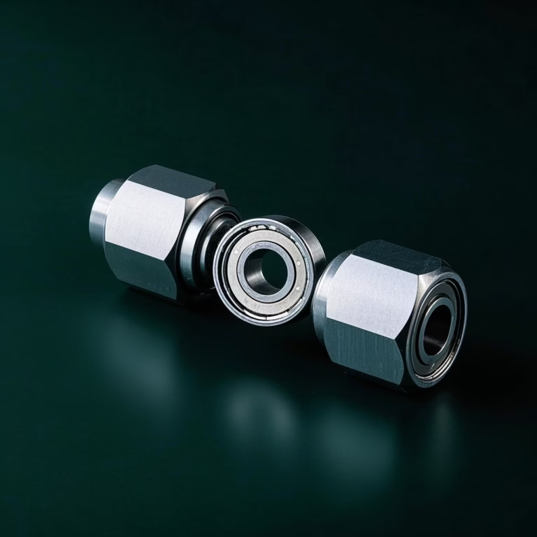
3. Bearing Installation
Ball bearings or roller bearings are inserted between the sleeve and body to facilitate rotation. High-quality bearings (e.g., ABEC-rated) are crucial for durability and low torque drag. Lubrication channels may be integrated to ensure long-term performance.
4. Sealing Mechanisms
A robust seal prevents fluid leakage. Common seal types include:
O-rings: Made of elastomers like Nitrile or FKM for moderate pressures.
V-Ring Packings: Triple-layer seals for high-pressure, high-moment applications.
Split Flange Seals: Combines an H-ring and O-rings for easy maintenance.
Materials like PTFE or Kalrez are used for extreme temperatures or chemical resistance.
5. Assembly
After individual components are manufactured, they are assembled to form the complete swivel ball joint:
Insertion of Ball into Socket: The ball is placed into the socket, ensuring proper fit and alignment.
Retention Mechanisms: Features such as snap rings, retaining clips, or threaded collars are used to secure the ball within the socket, preventing disassembly during operation.
Lubrication: Applying appropriate lubricants to reduce friction and facilitate smooth movement between the ball and socket.
Testing
Components are assembled under controlled conditions to ensure alignment. To ensure the swivel ball joints meet the required standards and specifications, rigorous quality control measures are implemented:
1.Dimensional Inspection
Verifying that all dimensions and tolerances are within specified limits using precision measuring instruments.
2.Material Testing
Conduct tests such as hardness tests, tensile tests, and metallo graphic examinations to confirm material properties.
3.1 Functional Testing
Simulating operational conditions to assess the joint’s performance, including range of motion, load-bearing capacity, and durability
3.2 Pressure Testing
Simulating operational pressures to check for leaks. Joints are subjected to 1.5x rated pressure for 30 minutes to detect leaks.
3.3 Torque Testing
Measuring rotational resistance to ensure smooth movement.
Fatigue Testing: Evaluating lifespan under cyclic loading.
Dynamic Endurance Testing: Simulates millions of cycles under load to assess fatigue resistance.
Salt Spray Testing: Evaluates corrosion resistance per ASTM B1176.
Surface Treatment
Surface treatments are applied to enhance the joint’s performance and longevity:
Grinding: Achieving a smooth surface finish on the ball and socket to reduce friction and wear.
Plating and Coating: Applying layers of materials such as chrome or zinc to provide corrosion resistance and improve surface hardness.
Heat Treatment: Processes like carburizing or nitriding are used to harden the surface while maintaining a tough interior.
Customization and Special Features
Threaded Ends: Some ball joints have threaded ends for easy attachment to other components.
Rubber Boots: Rubber boots can add to protect the joint from dirt and moisture.
Grease Fittings: Grease fittings allow for periodic re-lubrication to extend the life of the joint.
Innovations and Advancements in Swivel Ball Joint Manufacturing
Advancements in manufacturing technologies have led to improvements in swivel ball joint design and production:
Additive Manufacturing (3D Printing): Allows for the creation of complex geometries and internal structures that were previously difficult to produce, offering potential for weight reduction and enhanced performance.
Surface Engineering: Developments in coating technologies provide superior wear resistance and reduce maintenance requirements, extending the service life of the joints.
Quality Assurance and Compliance
Manufacturers adhere to strict standards to ensure safety and reliability:
ISO 9001: Quality management systems.
ASME B31.3: Process piping codes.
API 6A/6D: Standards for oil and gas equipment.
Regular inspections and certifications guarantee compliance with industry regulations.
Choosing the Right Swivel Ball Joint: A Buyer’s Guide
When selecting a swivel joint, consider:
Fluid Type: Corrosive, abrasive, or high-viscosity fluids require specialized materials.
Pressure/Temperature Range: Ensure compatibility with operational conditions.
Load Capacity: Heavy-duty applications demand reinforced designs.
Maintenance Requirements: Split flange joints offer easier servicing.
Common quality problems and solutions for swivel ball joints
1. Leakage caused by seal failure
Common causes:
Incompatibility of sealing materials and media (such as fluoro rubber in contact with strong oxidants)
Dynamic seal surface wear (surface roughness Ra>1.6μm)
Seal ring twists during installation (pre-compression exceeds 30%)
Solution:
Material upgrade:
Perfluoroether (FFKM) seals are used in high-temperature and high pressure scenarios, with a temperature resistance of 320℃
For corrosive media, polytetrafluoroethylene (PTFE) coated metal bellows are selected
Process optimization:
Laser cladding technology is used to prepare ceramic coatings on the sealing surface (thickness 0.3-0.5mm)
Introducing magnetic fluid seals (MFS), vacuum environment leakage rate ≤1×10⁻⁹ Pa・m³/s
Detection standard:
Helium mass spectrometer leak detection (ASTM E1226), leakage rate <5×10⁻⁷ mbar・L/s
2. Abnormal bearing wear
Typical phenomenon:
Sudden increase of 20% in rotational torque Above
Vibration acceleration>1.5g (ISO 1940 G2.5 grade)
Temperature rise rate>5℃/min
Root cause:
Insufficient lubrication (grease filling volume <30% of bearing space)
Foreign matter intrusion (such as metal debris particle size>50μm)
Irrational bearing clearance design (preload force>5N・m)
Solution:
Lubrication system upgrade:
Use dual-circuit lubrication (main grease lubrication + auxiliary oil mist lubrication)
Add molybdenum disulfide (MoS₂) nanoparticles (concentration 3-5%)
Pollution protection:
Integrated centrifugal separator (separation efficiency 99.9%@10μm)
Use labyrinth seal + magnetic filter combination.
Test verification:
Bearing life test (ISO 281), L10 life needs to be>10,000 hours.
3. Dynamic torque instability
Common scenarios:
Rotation speed>100rpm Torque fluctuation > 15%
Starting resistance increases suddenly in low-temperature environment (<-40℃)
Technical countermeasures:
Surface treatment optimization:
Use DLC (diamond-like carbon coating) to reduce friction coefficient to 0.05
Ion nitriding of ball joint surface (hardening layer depth 0.3mm)
Structural design improvement:
Increase static pressure support oil film (pressure 0.5-1MPa)
Use elliptical cross-section ball head (contact stress reduced by 25%)
Test method:
Torque curve collection (sampling frequency 100Hz), fluctuation coefficient <5%
4. Stress corrosion cracking (SCC)
Typical case:
Stainless steel joints for offshore platforms fail in Cl⁻ concentration > 500ppm environment.
Intergranular corrosion occurs in the weld heat affected zone (HAZ)
Prevention plan:
Material selection:
Use super austenitic stainless steel (such as AL-6XN)
Titanium alloy joints use β heat treatment (β-STA) to improve corrosion resistance.
Manufacturing process:
Solution treatment after welding (1050℃ insulation 2h)
Surface shot peening (coverage 100%, residual compressive stress>400MPa)
Environmental control:
Add corrosion inhibitor (such as molybdate concentration 50-100ppm)
Cathode protection (protection potential – 850mV vs Ag/AgCl)
5. Abnormal noise and vibration exceeding the standard
Diagnostic method:
Vibration spectrum analysis (1× frequency component ratio>70%)
Acoustic emission detection (AE signal energy>10⁶ counts)
Solution:
Dynamic balancing correction:
G0.4 level dynamic balancing (ISO 1940), residual unbalance <1g・mm
Structural damping optimization:
Add viscous damper (damping coefficient 50-100Ns/m)
Use carbon fiber reinforced composite (CFRP) shell.
Modal analysis:
Natural frequency avoids operating frequency ±20% (ANSYS modal analysis verification)
6. Failure caused by installation error
Common errors:
Coaxiality deviation>0.1mm (ISO 1101)
Uneven bolt preload (deviation > 10%)
Preventive measures:
Installation tools:
Use hydraulic tensioner (accuracy ±1%)
Laser centering instrument (coaxial control < 0.05mm)
Process specifications:
Adopt step-by-step tightening method (30% → 60% → 100% torque)
Thread coating anti-seizure agent (such as copper-based paste)
Verification method:
Strain gauge measurement (stress distribution uniformity > 95%)
7. Life expectancy is lower than design expectations
Data performance:
Actual life expectancy < 50% of design value (such as API 6A requires 500,000 cycles)
Improvement plan:
Fatigue strengthening:
Use ultrasonic impact treatment (UIP) to improve fatigue strength by 30%
Shot peening (Almen strength 0.3-0.5A)
Working condition monitoring:
Integrated strain sensor (accuracy ±0.01% FS)
Life prediction model (Miner linear cumulative damage theory)
Failure analysis:
Fractography SEM Analysis (crack growth rate > 10⁻⁶ m/cycle)
Q&A
Q1: How to solve the torque fluctuation problem of rotary joints?
A: Use high-precision grinding (Ra≤0.4μm) + optimize bearing preload (controlled at 1-3N・m), and use low friction coefficient coating (such as DLC).
Q2: How to prevent seal failure in a high-temperature environment?
A: Choose metal bellows seal + cooling channel design (such as spiral groove structure), combined with high-temperature grease (such as molybdenum disulfide).
Q3: How to reduce the cost of small batch production?
A: Use 3D printed prototypes (cost reduction of 60%) and use modular design to reduce mold investment.
Q4: How to quickly determine the leak location?
A: Use an infrared thermal imager (accuracy ±2℃) to detect temperature differences, or apply a fluorescent leak detection agent (black light excitation).
Q5: How to avoid torque surge in a low-temperature environment?
A: Use low-temperature grease (such as fully synthetic ester oil, pour point <-60℃) and perform a low-temperature start-up test (-50℃ insulation for 24h).
Q6: How to reduce the scrap rate in small batch production?
A: Implement SPC statistical process control (CPK>1.33) and 100% laser scanning inspection of key dimensions.
Conclusion
The manufacturing of swivel ball joints is a precise and multi-step process that combines advanced engineering techniques with rigorous quality control. By selecting appropriate materials, applying heat treatments, and ensuring meticulous assembly, manufacturers produce durable and reliable ball joints suitable for a wide range of applications. Manufacturing swivel ball joints require a blend of precision engineering, advanced materials, and rigorous testing. By following standardized processes and prioritizing quality, manufacturers deliver components that excel in performance and safety. For industries reliant on fluid transfer and rotational motion, investing in high-quality swivel joints is essential for minimizing downtime and maximizing efficiency.