
How To Make A Swivel Joint With Bearings?
Swivel joint with bearings are essential components in machinery, robotics, and industrial systems, enabling smooth rotational movement while supporting axial and radial loads. This guide provides a detailed, step-by-step approach to designing and building a Swivel Joint With Bearings. Whether you’re a DIY hobbyist or an industrial engineer, this resource will help you create high-performance swivel joints tailored to your needs.
1. Understanding Bearings for Swivel Joints
1.1. Introduction to Swivel Joint With Bearings and Their Applications
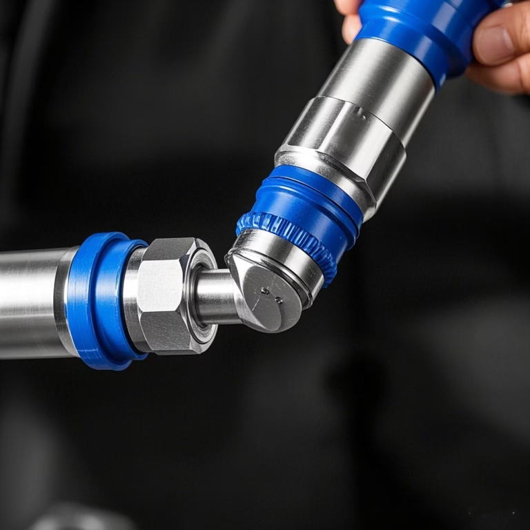
A swivel joint, also known as a rotary coupling or rotating union, is a mechanical device that allows fluid or torque transmission between two rotating components. Critical in applications requiring angular displacement while maintaining seal integrity.
Swivel joints are engineered for industries such as
Heavy machinery: Hydraulic cylinders in excavators and cranes;
Automotive: Steering systems and drive shafts;
Aerospace: Fuel lines in rotating engine components;
Medical devices: Surgical tools with rotating shafts.
This guide focuses on swivel joints incorporating spherical plain bearings (SPBs), which provide multi-axial rotation and high load capacity.
1.2 Types of Bearings
Selecting the right bearing type ensures optimal performance. Common options include:
1.2.1 Spherical Plain Bearings (SPBs) Structure
Comprises an inner ring with a convex outer surface and an outer ring with a concave inner surface.
Advantages: Accommodates misalignment up to 15° Self-lubricating designs for maintenance-free operation Applications: Agricultural equipment, construction machinery
1.2.2 Angular Contact Bearings
Structure: Asymmetric raceways support combined radial/axial loads.
Use Case: High-speed rotating shafts in CNC machines.
1.2.3 Thrust Bearings
Function: Handles axial loads only. Ideal For: Vertical pump shafts.
1.3 Bearing Selection Criteria
Load Capacity: Choose based on radial (Fr) and axial (Fa) forces. – Speed Rating: High-speed applications require precision bearings (e.g., ceramic hybrid bearings).
Environment: Corrosion-resistant bearings (e.g., stainless steel) for wet or dusty conditions.
2. Designing Your Swivel Joint With Bearings
2.1 Key Design Parameters
Bearing Fit: Use interference fits (e.g., H7/k6) for outer rings and clearance fits (H7/g6) for inner rings.
Seal Design: Integrate O-rings or labyrinth seals to prevent debris ingress.
Material Pairing: Match bearing materials with housing (e.g., steel bearings with aluminum housings).
2.2 CAD Modeling with Bearings
Use SOLIDWORKS or AutoCAD to simulate bearing performance under load.
Ensure adequate space for lubrication channels and seals.
3. Materials for Swivel Joints
3.1 Bearing Materials
Chrome Steel (AISI 52100): Cost-effective and durable.
Stainless Steel (440C): Corrosion-resistant for marine applications. Ceramic (Si3N4): Lightweight and heat-resistant for high-speed use.
3.2 Housing and Component Materials
Aluminum 6061: Lightweight and machinable.
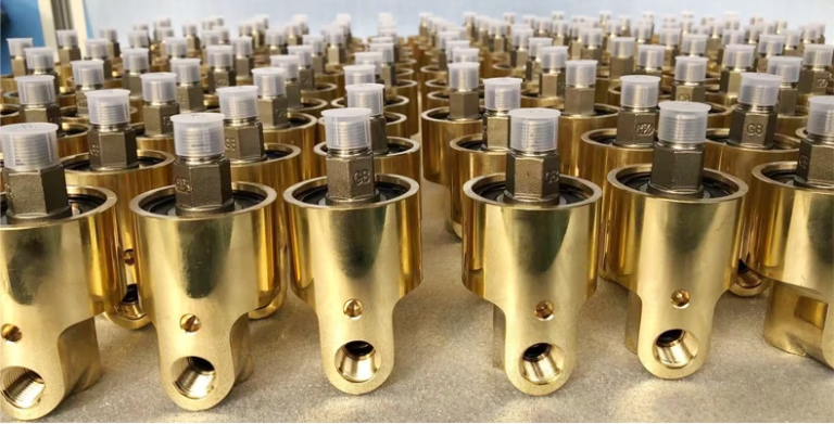
Brass: Non-magnetic and suitable for electrical applications.
Composite Plastics: Low friction (e.g., PTFE-lined housings).
4. Tools and Equipment
4.1 Machining Tools
Lathe: For turning bearing housings and shafts.
Milling Machine: To cut bearing seats and grooves.
Hydraulic Press: For precise bearing installation.
4.2 Measuring Instruments
Micrometer: Measures bearing dimensions (tolerance ±0.001mm). –
Dial Indicator: Checks bearing runout (<0.05mm).
Torque Wrench: Ensures proper fastener tightening (e.g., 10–15 N·m).
4.3 Advanced Technology
In the manufacturing process of rotary joints, metal cutting is generally used to complete the machining of component side holes and threads. Such as using a four-jaw chuck for clamping and turning on a regular machine tool, machining on a flower disc auxiliary fixture, or drilling holes on a drilling machine and completing them with a forming tap. These processing methods can easily lead to unstable product quality, low production efficiency, high labor intensity for workers, and difficulty in meeting design requirements for products with high demands.
At present, the most advanced processing method is to use specialized fixtures, programming, and forming tools to complete the machining of side holes and threads on CNC boring machines and machining centers. Although this can meet the design requirements, the clamping is complex, the calibration is difficult, and the equipment utilization rate is low, resulting in a significant increase in equipment costs, tool costs, and labor costs.
4.4 Advantage
Our flange-connected multi-purpose side hole machining mechanism has a simple and flexible structure, which can quickly clamp and position the parts, achieve rotation at the machining site, and have good universality and interchangeability. The machining mechanism uses conventional cutting tools to cut the side holes and threads that need to be machined, shortening the auxiliary time, improving machining efficiency and accuracy, greatly reducing the labor intensity of workers and the investment of forming tools, and ensuring the design requirements.
The structure is simple and flexible, with quick clamping. It is connected to the main shaft flange through the base. By replacing the positioning plate and adjusting the counterweight, various components with similar specifications can be processed, with good interchangeability and can be adjusted according to needs. After implementation, the machining quality and stability of the side holes and side hole threads of the rotary joint components have been improved, and the machining surface has a good appearance quality, and accuracy. The implementation has greatly improved processing efficiency, reduced the cost of equipment, cutting tools, labor, and other auxiliary materials, shortened product delivery time, and improved economic benefits. The processing technology of this structure is still pioneering in the rotary joint manufacturing industry.
5. Step-by-Step Construction Guide
5.1 Precision Casting and Forging
By mold casting or hot forging, the dimensional accuracy of the blank is ensured and the subsequent machining allowance is reduced.
5.1.1 Machining
Turning/milling: Use CNC machining centers to machine flow channels, bearing holes, and sealing surfaces with an accuracy of 0.01mm.
Heat treatment: Salt bath nitriding or vacuum quenching is used to improve surface hardness (HV ≥ 800) and fatigue strength.
Grinding: The sealing surface is machined by a surface grinder with a roughness Ra ≤ 0.4 μ m.
5.1.2 Special arts and crafts
Sealing surface treatment: laser texturing or electrochemical polishing to enhance lubrication and sealing properties.
Coating: DLC (diamond-like carbon) or CrN coating to enhance wear resistance.
5.2 Installing Bearings
Preheating: Heat the housing to 80°C (176°F) for thermal expansion.
Press-Fitting: Use a hydraulic press to seat bearings (force ≤5 tons).
Alignment: Ensure bearings are perpendicular to the shaft using a dial indicator.
5.3 Assembling the Swivel Joint
Shaft Insertion: Slide the shaft into the inner bearing race.
Seal Installation: Press-fit O-rings into grooves and apply silicone sealant.
Testing: Rotate manually to check for smoothness (torque <1 N·m).
5.4 Quality inspection and verification
5.4.1 NDT
Ultrasonic testing: detects casting defects (such as shrinkage and cracks) with a sensitivity of ≥ 2mm for flat-bottomed holes.
X-ray inspection: Verify the quality of the weld seam and comply with ASME BPVC standards.
performance test
Pressure cycle test: Load 10000 times in cycles of 0~35MPa to test fatigue life.
Thermal shock test: Simulate alternating cold and hot temperatures (-40 ℃~200 ℃) to verify sealing stability.
5.4.3 Certification standards
Complies with JB/T 8725-2013 “Rotary Joints” or API 682 standards, and provides third-party testing reports.
6. Optimizing Performance
6.1 Lubrication Strategies
Grease Type: Use lithium-based grease for general applications, or molybdenum disulfide for high loads.
Grease Quantity: Fill 30% of bearing space to prevent overheating.
6.2 Dynamic Balancing
Use a balancing machine to reduce vibration (G2.5 balance grade recommended).
6.3 Load Testing
Gradually apply loads up to 150% of rated capacity to validate durability.
6.4 Design Considerations for Optimal Performance
6.4.1 Load Capacity Static
Load: Calculate using the formula:
C₀ = f₀ * Z * D * B
Where f₀ = material factor, Z = number of balls, D = ball diameter, B = bearing width.
6.4.2 Misalignment Compensation
SPB Advantage: Maintains function even with 3°–15° misalignment.
6.4.3 Thermal Expansion
Mitigation: Use split flange designs to accommodate temperature-induced expansion.
7. Testing and Quality Control Protocols
7.1 Pressure Testing
Hydrostatic Test: Pressurize to 1.5x rated capacity for 5 minutes.
Leak Detection: Use a helium mass spectrometer to trace leaks.
7.2 Wear Testing
Cyclic Loading: Run 1 million cycles at 80% load to measure wear patterns.
8. Maintenance and Troubleshooting Tips
8.1 Preventive Maintenance
Lubrication: Relubricate every 500 hours (or as recommended by OEM).
Inspection: Check for brinelling or raceway corrosion.
8.2 Common Failures
Seal Leakage: Cause: Over-tightening during assembly.
Fix: Replace seals and use a torque wrench.
Bearing Lockup: Cause: Inadequate lubrication.
Fix: Flush with solvent and relubricate.
9. Industry-Specific Use Cases
9.1 Oil and Gas Drilling
Application: High-pressure mud swivels
Requirements:
Pressure Rating: 10,000 PSI (690 bar)
Material: Inconel for corrosion resistance
9.2 Robotics
Application: Rotary joints in articulated arms
Requirements:
Precision: <0.1° angular deviation
Speed: Up to 200 RPM
10. Advanced Applications
10.1 Multi-Bearing Configurations
Dual-Row Ball Bearings: Increase load capacity by 40%.
Angular Contact Bearings: Handle combined radial and axial loads.
10.2 Custom Bearing Solutions
Split Bearings: For easy maintenance in hard-to-reach areas. –
Self-Aligning Bearings: Compensate for shaft misalignment (<2°).
11. Common Issues and Solutions
11.1 Bearing Noise
Cause: Improper alignment or insufficient lubrication.
Fix: Re-align bearings and re-grease with high-viscosity grease.
11.2 Premature Wear
Cause: Contaminant ingress or overload.
Fix: Upgrade seals and implement load monitoring systems.
12. Maintenance Best Practices
12.1 Inspection Schedule
Monthly checks for vibration, temperature, and lubrication levels.
12.2 Bearing Replacement
Replace bearings when noise or vibration exceeds baseline by 20%.
13. Case Studies
13.1 Hydraulic Machinery Industry – Excavator Rotating Platform
In the field of construction machinery, the 360-degree rotating platform of excavators needs to be connected to the hydraulic oil circuit of the upper and lower body through a rotating joint. The integrated rotary joint developed by a certain heavy industry enterprise adopts a three-layer sealing structure: the innermost layer is a tungsten carbide alloy shaft sleeve, the middle layer is equipped with a double lip fluoro rubber sealing ring, and the outer layer is equipped with a labyrinth dust cover. This design breaks through the limitations of traditional single seals and maintains a leakage rate of 0.01ml/min after 2000 hours of continuous operation, extending the lifespan of traditional products by 40%. At the Shanxi coal mine site, the application of this technology has extended the maintenance cycle of excavators from once a month to quarterly maintenance, saving approximately 150000 yuan in annual maintenance costs.
13.2 Food Processing Industry – Aseptic Filling Equipment
A certain dairy product enterprise adopts sanitary grade rotary joints in high-speed filling machines, and its innovation lies in the use of 316L stainless steel material combined with mirror polishing technology (Ra ≤ 0.4 μ m), internal design of self-cleaning flow channel structure, and configuration of corrugated tube mechanical seals. Through CFD fluid simulation optimization, the shear force of the material during rotation is reduced by 65%, effectively preserving the nutritional components of dairy products. At a factory in Guangdong, the equipment achieved a filling speed of 12000 bottles per hour and passed FDA certification. The total bacterial count was controlled below 5CFU/100ml, which is three orders of magnitude higher than traditional equipment.
13.3 Petrochemical Industry – Offshore Drilling Platforms
The rotary blowout preventer system of deep-sea drilling equipment adopts multi-stage sealed rotary joints, and its core technology includes high-temperature (250 ℃) metal corrugated pipe sealing, a hydraulic balance compensation device, and an online monitoring system. In the application of Nanhai Oilfield, the device successfully responded to a high-pressure environment of 150MPa and achieved continuous 72-hour fault-free operation. By integrating pressure sensors and temperature sensors, the system can monitor the sealing status in real time, and predictive maintenance reduces downtime by 80%. Compared to traditional products, this solution increases the sealing life from 3 months to 18 months and reduces the cost of single well operations by approximately $2 million.
14. Future Innovations
14.1 Smart Bearings
IoT-enabled bearings with built-in sensors for real-time performance tracking.
14.2 Advanced Materials
Graphene-coated bearings reduce friction by 50% compared to traditional designs.
15. FAQ
Q1: Can I use skateboard bearings for a swivel joint?
A: Yes—608 skateboard bearings are cost-effective but less durable than industrial-grade bearings.
Q2: How to choose the right bearing size?
A: Calculate the required load capacity and shaft diameter using ISO 281 standards.
Q3: What’s the difference between radial and thrust bearings?
A: Radial bearings handle side loads, while thrust bearings manage axial forces.
Q4: Can I use standard bearings in a swivel joint?
A4: No. Swivel joints require bearings with spherical contact surfaces to handle misalignment.
Q5: What causes swivel joint vibration?
A5:Common causes include improper lubrication or excessive misalignment.
Q6: How often should I replace seals?
A6:Replace every 2,000–3,000 operating hours under normal conditions.
16. Conclusion
Elevating Your Engineering with Custom Swivel Joints By mastering swivel joint fabrication, engineers can unlock performance improvements in critical applications.
Key takeaways
Material Selection: Prioritize self-lubricating composites for harsh environments.
Precision Manufacturing: Invest in CNC machining for tight tolerances. Proactive Maintenance: Extend lifespan through regular inspections.
Creating a swivel joint with bearings requires precision engineering and careful component selection.
Whether for prototyping or industrial use, a well-built bearing swivel joint delivers reliability and performance.