
How H Series Hydraulic Rotary Unions Simplify Installation and Boost Performance
In today’s industrial landscape, H Series Hydraulic Rotary Unions are the power source behind heavy machinery, robotics, and advanced automation equipment. Central to these systems is the hydraulic rotary joint, the critical component responsible for transferring pressurized fluid from a stationary source to a rotating part. However, complex, multi-functional machinery often requires intricate fluid paths, leading to challenging installation, frequent misalignment, and premature component failure.
This is where the H Series Hydraulic Rotary Unions emerge as a game-changer. Engineered for versatility, ease of integration, and extreme durability, the H Series is designed to address the most pressing challenges faced by engineers, technicians, and procurement managers alike.
This comprehensive expert guide will systematically analyze the technical advantages of the H Series, detailing exactly how its innovative design simplifies complex rotary manifold setup and provides the robust performance required for modern industry. We will explore key features that contribute to easier installation, extended service life, and significant cost savings.
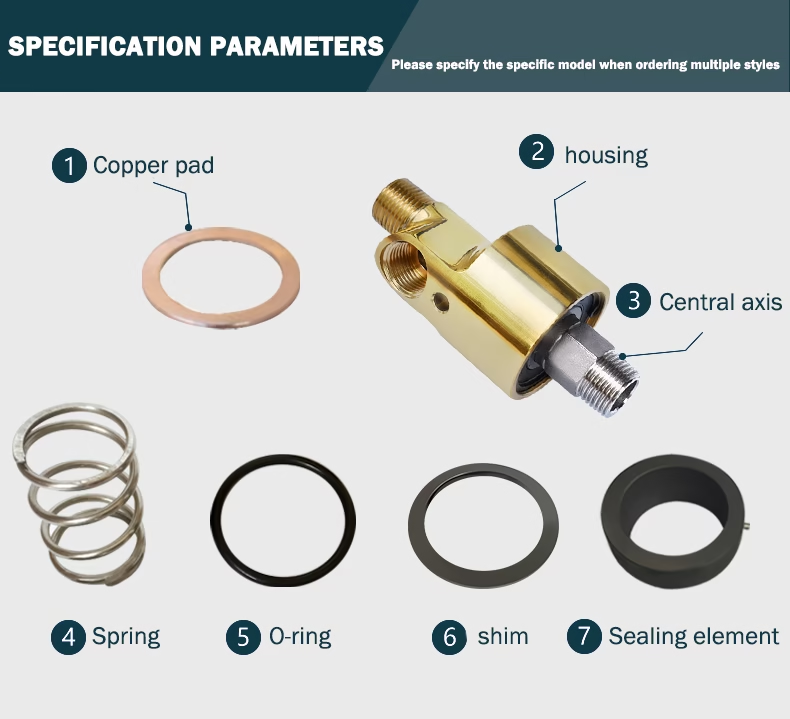
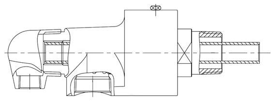
Internal structure of the product
The structure of the H Series Hydraulic Rotary Unions includes a shell, shaft, bearing, shaft clamp, empty clamp, sealing ring, O-ring, baffle, copper baffle spring, oiling nozzle, etc.
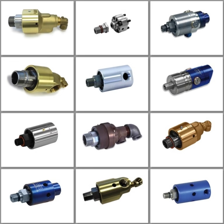
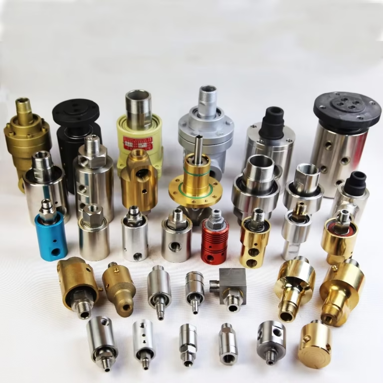
 Product Type
H Series Hydraulic Rotary Unions’ connection methods are divided into threaded type and flange type.
1. One-way flow rotary joint
Symbol: HD-type rotary joint
Connection method: threaded connection
Symbol: HD-F type rotary joint
Connection method: half-split ring flange connection
2. Two-way flow inner tube fixed rotary joint
Symbol: HS-GF type rotary joint
Connection method: half-split ring flange connection, Two-way flow inner tube fixed rotary joint
Symbol: HS-G type rotary joint, HS-X type rotary joint
Connection method: threaded connection
4. Two-way flow inner tube rotary joint
Symbol: HS-XF type rotary joint
Connection method: half-split ring flange connection
Applications Across Industries
The H Series Hydraulic Rotary Unions’ adaptability makes it suitable for diverse sectors. Let’s explore key applications:
A. Construction and Mining Equipment
Excavators and Cranes: Transfer hydraulic power to rotating superstructures.
Drill Rigs: Enable continuous rotation during drilling operations.
Concrete Mixers: Facilitate drum rotation for material mixing.
B. Manufacturing and Automation
Rotary Tables: Power index tables in CNC machining centers.
Indexing Machines: Synchronize rotation with hydraulic actuators.
Robotics: Drive rotating joints in industrial robots.
C. Energy and Oil/Gas
Drill Ships and Rigs: Transfer fluids to rotating drill bits.
Wind Turbines: Enable yaw and pitch control systems.
Pipeline Maintenance: Power rotating tools for inspection and repair.
D. Agricultural Machinery
Irrigation Systems: Rotate sprinklers and pivot points.
Harvesters: Drive rotating blades and conveyor belts.
Installation steps
1. Clean the shaft head, no burrs, sealing residues;
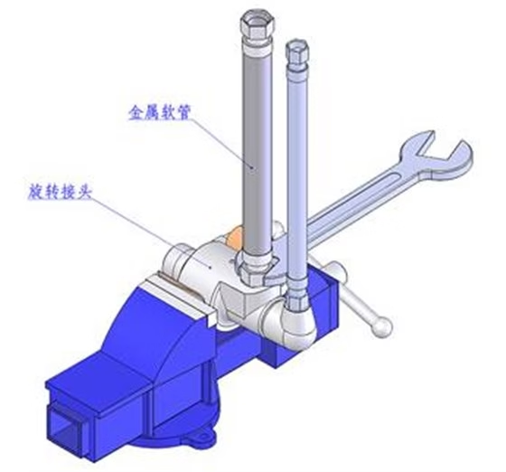
2. Clamp the joint with a bench vise and install the metal hose
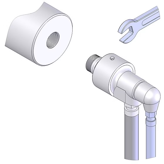
3. Connect the inner tube;
4. Connect the joint to the shaft head. If it is a flange connection, first put the sealing gasket (copper gasket) in the shaft hole, then effectively connect the joint with the inner tube (if the inner tube is a siphon elbow, make sure the siphon nozzle is vertically facing downward), then use screws to connect the quick-change flange and half ring to the shaft head, pre-tighten diagonally, and then tighten evenly. The torque should be the same. After installation, there should be a gap between the quick-change flange and the shaft head flange. If it is a threaded connection, add sealing packing.
Note: The Flange type needs to have a sealing gasket.
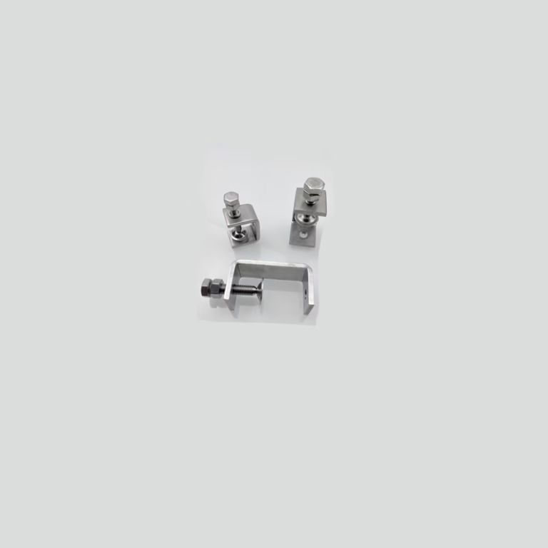
5. Stop rotation; if there is a lifting ring, use the lifting ring to stop rotation. The diameter of the stop rod is 2~3mm smaller than the diameter of the lifting ring. Based on stopping rotation, ensure the free swing of the joint.
Implementation of safety measures
During the installation process, be sure to comply with the safety operating procedures to ensure the safety of personnel and equipment.
1. Always apply thread sealant or PTFE tape when installing a threaded rotary joint.
2. Prepare the appropriate sealing pads—such as copper gaskets, spiral wound metal gaskets, or PTFE pads—before installing rotary joints with flat seals.
3. Thoroughly remove hard particles, dirt, and impurities in the pipe and roller, and ensure that the end of the roller shaft is clean.
4. Connect the metal hose (or transition joint) to the rotary joint on the vise. The specific steps are as follows:
(1) First, use the vise to firmly clamp the rotary joint.
(2) Then, apply thread sealant or wrap raw tape on the wall hole and elbow of the rotary joint to enhance the sealing of the connection. Then, install the metal hose in the corresponding position and ensure that it is tightened.
Precautions
1. Ensure that no foreign matter contaminates the sealing surface before installation. For joints with inspection holes, please make sure the inspection holes face downward during installation. When installing the pipeline, avoid installing heavy objects such as valves on the H-type rotary joint.
2. In the case of threaded installation, the direction of the thread should be easy to tighten (smooth) relative to the direction of rotation. The rotation direction of rollers, drums, etc., viewed from the installation direction of the H-type rotary joint, should be: “clockwise for left thread, counterclockwise for right thread”.
3. Please use flexible pipes to connect the H-type rotary joint and the piping part. Please avoid using steel pipes to directly install the pipes, which will constrain the joints. When stopping the H-type rotary joint, allow it to stop freely without applying any external constraint.
4. Please avoid using the highest speed under the highest operating pressure conditions. When operating under high temperatures with ball bearings, apply grease before use. Reapply grease periodically based on usage frequency and operating time.
5. Remove the plug before applying grease. Do not leave the rotary joint idle for extended periods when it is stopped. Otherwise, it may rust and cause fluid leakage.
6. For joints with inspection holes, if fluid leaks from the inspection holes, it is time to replace them. In the event of a malfunction, please repair or replace it with a new one in time. Please do not continue to operate in a state of fluid leakage; otherwise, it will cause a major accident.
Maintenance and care
Proper maintenance and care of the rotary joint are just as critical as its installation. Regularly inspect the mounting status of the metal hose and stop rod to ensure they remain secure and free from friction. Monitor the operating environment to avoid excessive vibration or impact, which can compromise stability and shorten service life. Lubricate the rotary joint periodically to minimize friction and wear, thereby enhancing its durability and long-term performance.
1. Under the action of the medium pressure, impurities may squeeze into the sealing surface, causing the seal to wear rapidly and leak. Therefore, a filter device should be installed for filtering before operation. After the filtering is completed, if conditions permit, the filter device can be removed to reduce the pipeline resistance.
2. Protect the rotary joint from bumps and severe vibrations.
Handle the rotary joint with care, as its sealing elements are typically made of non-metallic materials that can be easily damaged by impact. Avoid any collision or rough handling. For rotary joints with threaded connections, take extra caution to prevent thread damage and ensure smooth installation.
3. For rotary joints equipped with oil-filling holes, lubricating oil or grease of appropriate specifications should be added regularly to extend their service life.
4. When replacing seals, ensure that the sealing surface is not bumped or scratched, and take measures to prevent foreign matter from entering.
5. Replace all sealing rings at the same time during maintenance to avoid mixing old and new seals when the rotary joint uses a sealing ring.
Stop the rotary joint immediately if any leakage is detected, and contact a professional technician promptly to prevent further damage to other components.
Common Issues and Solutions
Fluid leakage issues are typically caused by worn seals or damaged housing. In such cases, it is recommended to replace the seals or housing to repair the leak.
High-friction phenomena may stem from contaminated bearings or insufficient lubrication. An effective solution is to clean the bearings and replenish the lubricant, thereby reducing operational resistance.
Selection Guide: Choosing the Right H Series Union
Selecting the optimal H Series union involves evaluating several factors:
A. Pressure and Speed Requirements
Match the union’s pressure rating to your system’s maximum operating pressure.
Ensure speed ratings align with rotational speeds (e.g., high-speed vs. standard).
B. Passage Configuration
Determine the number of fluid passages needed (e.g., 2-way for simple circuits, 12-way for complex systems).
Consider media compatibility (hydraulic oil, water, coolant).
C. Environmental Conditions
For extreme temperatures, opt for high-temperature seals and materials.
In corrosive environments, choose stainless steel or coated components.
D. Maintenance Accessibility
Prioritize unions with easy access to seals and bearings for quick maintenance.
Consider modular designs for simplified repairs.
Conclusion
The H Series Hydraulic Rotary Unions represent the future of industrial fluid transfer. They solve the twin challenges of simplifying complex installations and ensuring robust, reliable, high-pressure performance. For engineers, they offer technical precision and design flexibility. For technicians, they provide easier, faster installation and less troubleshooting. And for procurement managers, they represent a strategic investment that maximizes uptime and dramatically lowers the total cost of ownership.
By choosing the H Series, you are choosing a component that elevates the performance of your entire machine, ensuring stable operation and a decisive edge in productivity.
Call to Action:
Ready to optimize your H Series Hydraulic Rotary Unions systems? Explore our H Series catalog or contact our experts for a customized solution tailored to your needs.